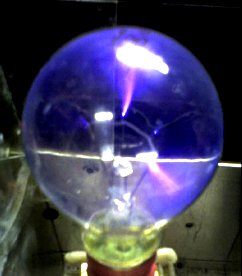
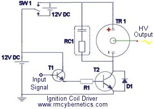
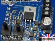
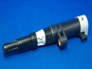
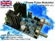
 There are all sorts of ways to make a plasma globe. This page deals will detail how to make one using a small amount of easily obtainable components. A normal transparent light bulb can be used as a plasma globe simply by connecting it to a high voltage, high frequency source. Most light bulbs contain low pressure Argon gas to prevent the hot filaments from burning. Fortunately this arrangement is also ideal for making contained arcs of plasma. The power supply required for the plasma globe would preferably be a high voltage, high frequency AC type, which could be made from an ignition coil, like the ones used in the Homemade Tesla Coil project. The schematic below shows a driver circuit, for more details see the Ignition Coil Driver page. We also sell a ready made ignition coil driver (shown in the pictures) which also includes extra features.
| WARNING: High Voltage Devices! |
Assembling the Plasma Globe
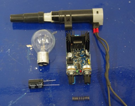 The following parts are used for the video demo of this project;
- HV Spark Coil (ignition coil)
- Incadescent lightbulb
- Spring (or short wire)
- PWM Drive Circuit
- 1000uF Electrolyitic Capacitor
First the spring must be attached to the bottom of the light bulb; this can be done using a bit of tape. The spring is used to ensure a connection between the bottom of the bulb and the high voltage output within the end of the ignition coil. Next, the bulb and spring are fixed tot he end of the ignition coil with some more tape.
The ignition coil is connected by two wires to the PWM circuit at the L+ and L- terminals, and the power supply is connected to GND and V+. Also connected to V+ and GND is the electrolytic capacitor. This is connected close to the circuit board and is used to keep the DC input stable. It is important to note that the orientation of the capacitor must be correct. To know which way around it should go look for the longer leg (which indicates the positive) there is also often a stripe on the side of the capacitor to indicate the negative side.
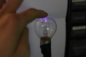 The settings on the PWM circuit will need to be adjusted so that good streamers become visable in the coil. Always begin with the duty setting at zero then slowly turn it up to around 50%. The frequency setting is then adjusted while observing the apperance of the plasma inside the lightbulb. At some frequencies no plasma will be seen, while when at the right frequency there should be lots of streamers dancing around inside the bulb. The frequency needs to be fairly high and the buzzing sound from the coil will become so high its is amost inaudiable.
When operating the circuit great care must be taken as the ignition coil could output around 20-30kv when using around 15V, 5A from the power supply.It should not be touched as it will give a nasty shock.


No. Plasma globes use high frequency AC, a VDG is DC. The globe might glow, but you wont get the streamers you normally see.
Can a VDG be used to run a plasma globe?
I don’t understand.
I use it with plasma speaker using an audio-computer calling to enter the fate of the driver at the exit of the speaker?
A squarewave signal is applied to it so that power to the ignitioncoil is rapidly switched on and off. See the ignition coil driver page for more info.
on the base of T1, what is the ‘signal input’/what is it for/etc.?
Yes this would work but there is a risk of damaging your PC. I reccomend that you use an optoisolator between your PC and the circuit.
epx101 returning here 🙂

hey!, can i use tone generator of my pc ??
then connect it to the signal input.
cause the tone generator produces clicks at my speaker and it also have square wave
its bout 20,000hz or higher its a self resonating flyback driver coupled with a neon golbe on the primary wires, works very well
Yes it is enough. The frequency must be quite high too.
dear rmc would 30kv be enought to run a light bulb plasma effect
my generation source is a self resonating single based transistor driver a very simple one but im not sure if it will produce enough voltage